CAUTION: Installing suspension components can be dangerous and result in serious injury or death. Improper installation also can cause damage to your vehicle and other property, and result in an unsafe operating condition or void the component manufacturer's warranty. Before beginning installation, you should read and observe the component manufacturer's warnings and instructions in addition to the method and procedures described in this article. Observing such warnings and instructions is important to the safe installation of suspension components and safe performance of your vehicle suspension.
Year: 2013 thru 2016
Make: Scion/Subaru
Model: FR-S/BRZ
Front and Rear Suspension Components
- Front Camber Bolts (2 lower position): SPC 81305, 14mm EZ CAM XR
- Rear Adjustable Lower Toe A arm (2) : SPC 67660
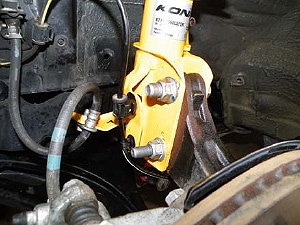
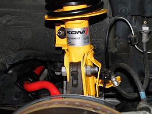
- Front Sealed KONI Sport Shocks: 8741-1560L/R
- Rear Sealed KONI Sport Shocks: 8041-1416
- Front Eibach Springs (2): 82105.001
- Rear Eibach Springs (2): 82105.002
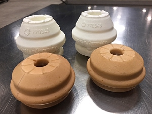
- Front Bumpstops (2): 1J0412303 (770343)
- Rear Bumpstops (2, short): BS7701
Front Suspension Installation
Note: Nut/bolt sizes are shown in mm next to item note.
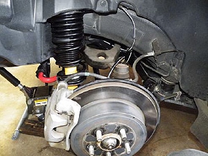
- 1. Remove the following items per side.
- Lug nuts (19).
- Brake hose removed from bracket on shock assembly (12).
- Two strut bolts (19).
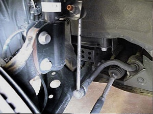
- Two sway bar link nuts (17) with Allen (6), if necessary.
- Two plastic fasteners for the ABS line. Use screwdriver on backside to compress tabs.
- Two plastic fasteners for lower plastic panel covering sway bar mount. Swing panel out of way.
- Three upper strut nuts (12).
- One bolt towards the front for the sway bar mount (14).
- One nut underneath towards the rear for the sway bar mount (12). This can be accessed from below through a hole in the frame member by removing the two bolts (10) holding that side of the flexible cover.*
- Remove sway bar from passenger side with shock assemblies out on both sides. Twist ends to the rear.
*Note: If the cover does not give enough access, then the metal shield with four cover bolts (10), six shield bolts (12), and six plastic fasteners may have to be removed. One each of the three plastic fasteners on each side is underneath the fender liner towards the front.
- 2. Disassemble OEM shock assembly.
- Remove assembly from vehicle.
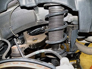
- Lightly compress with spring compressor.
- Remove center nut (17). Need to use an external socket to access the Allen internal (6) to hold rod in position.
- Keep upper mounting bearing for use with new unit. Note orientation position of end of upper part of spring.
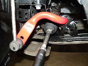
- Installation of Eibach Front Sway Bar
- Install new urethane bushings (with grease) and OE mounts onto the sway bar. Flanged end butts up against the ring on the sway bar.
- Install links to new sway bar on outermost setting (softest). Leave loose for now.
- Install sway bar from passenger side with shock assemblies out on both sides. Twist ends to the rear.
Rear Suspension Installation
Note: Nut/bolt sizes are shown in mm next to item note.
- 1. Remove the following items per side:
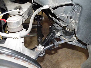
- Inner rear toe link. Mark location for inner bolt (22) with nut (19).
- Outer rear toe link tie rod end (17) with retainer clip instead of a cotter pin.
- Shock mounting bolt in lower control arm (17).
- Trunk floor piece and six plastic fasteners to remove side panel for access to the top of the shock assembly.
- Three upper shock nuts (12).
- Sway bar link ends (14).
- Lower control arm inner and outer (17).
- Parking brake cable bracket (12). Will need to move cable around to clear tie rod end.
- Two bolts towards the rear for the sway bar mount (12).
- 2. Disassemble OEM shock assembly.
- Remove assembly from vehicle.
- Lightly compress with spring compressor.
- Remove center nut (14). Need to use an external socket to access the Allen internal (5) to hold rod in position.
- Keep upper mounting for use with new unit. Note orientation position of end of upper part of spring.
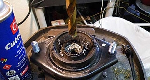
Note: The upper mounting OEM hole size is 0.410 inch. The KONI shock shaft is 0.460 inch (+0.050-inch difference). Drill upper mount on center with a 15/32 (0.469) inch drill.
- Installation of Eibach Rear Sway Bar (82105.320R)
- Install new urethane bushings (with grease) and OE mounts onto the sway bar. Flanged end butts up against the ring on the sway bar.
- Install links to new sway bar on outermost setting (softest). Leave loose for now.
- Install sway bar from either side with shock assemblies out on both sides. Twist ends to clear exhaust on L side.
- 3. Install SPC rear toe link (67655) and lower control arm (67660).
- Set the new toe link to the approximate length of the OEM toe link.
- Install the inner end of the new toe link with the optional bracket on top. Leave loose for now.
- Install the tie rod end (18) of the toe link. Torque to 45 ft-lbs and use OEM clip instead of the SPC cotter pin.
- Install the inner end (17) of the new lower control arm. Leave loose for now.
- 5. Final assembly.
- Once all bolts are loosely in place for both sides, lower vehicle. If possible, move vehicle at least 50 feet in both directions to settle the entire rear suspension to its new normal ride height.
- Tighten all of the loose components:
- Inner toe link with cams facing upward toward trunk floor
- Inner lower control arm
- Outer lower control arm with cams facing outwards
- Lower shock assembly bolt
- Upper and lower sway bar links
Suggested Baseline Settings After Alignment
- Front Camber: -3.0 degrees (Confirm wheel and tire clearance near spring perch before driving, 3mm minimum clearance recommended.)
- Front Caster: 5.4 degrees(left)/5.5 degrees (right)
- Front Toe: Zero
- Rear Camber: -2.25 degrees
- Rear Toe: 1/8-inch total toe-in
- Tire Pressures: 35 psi all around (baseline, tune to surface and driver)
- Front and Rear Sway Bar: Set at outermost adjustment or softest setting
- Front Shocks: 1.0 turns (of 2.5 turns total available)
- Rear Shocks: 1.5 turns (of 2.5 total available)
General Notes and Comments (some are repeated from above)
- Front shock assembly not marked by KONI L or R. Need to visually verify by comparison with removed OEM shock assembly.
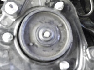
- The front shock assembly upper bearing mount has exposed bearings. For the moment, the OEM rubber cover was cut with a "+" and pushed down around the adjustment shaft. A better long-term solution would be a cap with a proper hole in it.
- The rear shock assembly upper mounting OEM hole size is 0.410 inch (11). The KONI shock shaft is 0.460 inch +0.050 inch difference (12). Drill upper mount on center with a 15/32 (0.469) inch drill.
- After the alignment is completed. The steering angle must be re-calibrated for the OEM stability control to operate normally. If this is not done, the stability control may interfere with performance driving scenarios. For this particular vehicle, the steering angle was -3.2 degrees off until re-calibrated.
Additional SPC Installation Sheet and Video Guides
Rear Adjustable Camber Arm (67660) Instruction Sheet , Video
Rear Adjustable Toe Arm (67655) Instruction Sheet
Note: The offset toe bushing included with the Rear Adjustable Camber Arm is not required and may be discarded when the Rear Adjustable Toe Arm is used.
Was this post helpful?
384 of 757 people found this post helpful

